Identify the driving feature
The tang provides the contact surface for the installation tool.

TANGED WIRE INSERT
An established approach to thread reinforcement.
The tang transfers torque to drive the insert into the installation hole. Plan both tang break-off and recovery as separate process steps.
DESIGNED FOR CONNECTION
A tanged wire insert has a transverse installation tang at one end. The tool uses it to drive the insert into the hole; it is then broken off and recovered as specified. For thread repair, assess damage and remaining wall thickness before planning drilling and tapping.
The tang provides the contact surface for the installation tool.
Suitable for new-thread reinforcement and for assessing repairs to damaged threads.
Use separate checkpoints for tapping, installation, tang break-off and recovery.
01 / STRUCTURE
The insert structure determines how tanged wire inserts connect and install.
Tanged structure; remove the installation tang after fitting as specified.
For connections requiring screw locking.
Confirm thread size, engagement length and installation conditions.
Related product:Explore the related product →
02 / MATERIAL
These material options are discussion points; not every model is available in every combination.
Stainless steel options. Select with regard to the environment, mating screw and corrosion requirements.
A stainless steel option; confirm the grade and applicable material standard.
An option to discuss where resistance to galling is required.
A nickel-alloy option to discuss for high-temperature conditions.
Discuss weight, media and electrochemical compatibility.
Provide operating temperature, loads and material specifications.
03 / SURFACE
Consider friction, corrosion resistance and identification in the operating environment. Confirm available combinations with an engineer.
An option for controlling friction and assembly consistency.
Consider high-temperature operation and mating-thread compatibility.
A surface-treatment option for stainless steel; not equivalent to nickel plating.
Confirm friction, corrosion and temperature requirements for the selected coating system.
Helps identify models or batches; not a substitute for material documentation.
Confirm separately for the environment, applicable standards and supply requirements.
INSTALLATION
Prepare the hole before installing the insert. These seven steps show a through-hole installation, including tang break-off, recovery and inspection.
Compare tangless installation →Cutting tools, gauges and installation mandrels are shown separately
The gray section represents the parent material and hole
Tanged installations require separate tang recovery
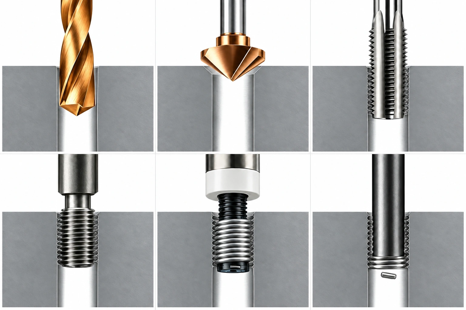
Select the drilling diameter for the thread and parent material, then drill through the workpiece. Check rear clearance and remove chips and burrs at both ends.
Steps 01–07 use a through-hole example.Chamfer and deburr the entry as specified, then inspect the through-hole exit to keep both installation and tang-recovery paths clear.
Chamfer requirements depend on the selected insert system and drawing.Use a matching STI tap to produce the installation thread. Cutting or forming must be compatible with the parent material and insert system.
A conventional screw tap of the same nominal size is not a substitute.Clean the hole and use a matching STI gauge to check the installation thread. If coating or treatment follows, reassess its dimensional effects.
This checks the installation hole before the insert is fitted.Use the matching tool to drive the tang and install to the specified depth. Avoid cross-threading, excessive compression and premature tang breakage.
Set the depth according to the drawing, entry geometry and tool depth stop.Ensure sufficient downward travel for the break-off tool. Break the tang as instructed, recover it through the hole exit and verify recovery.
Through-holes provide space for tool travel and tang removal; confirm rear access is available.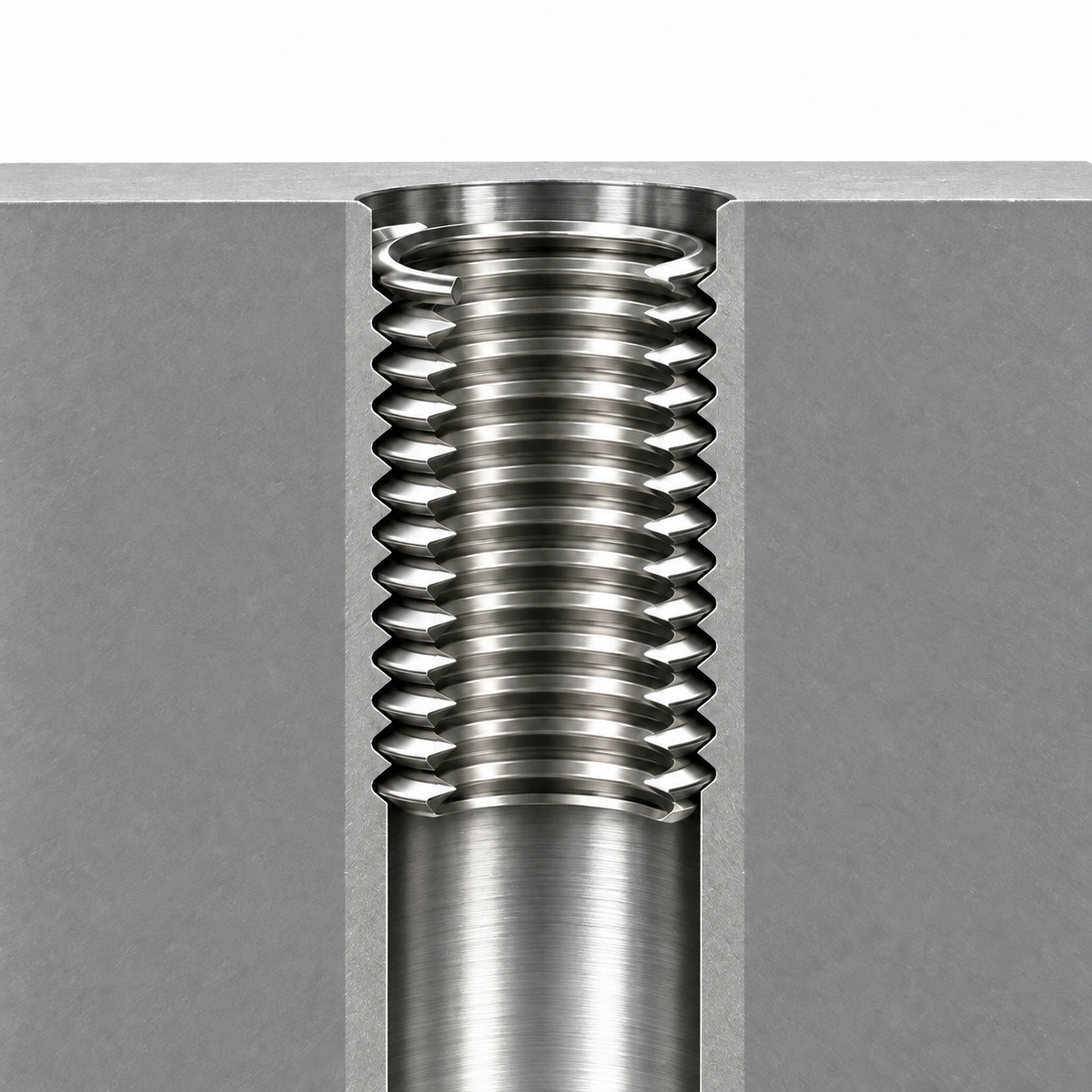
Inspect depth, insert condition and both ends of the through-hole. Confirm no tang or chips remain and record tang recovery. Complete fit or locking checks as specified.
Follow the locking insert's acceptance procedure; do not force a standard GO gauge through a locking coil.Check tang break-off clearance first. Through-holes help provide tool travel and a recovery path. Insufficient bottom clearance in a blind hole may prevent break-off or trap the tang. Assess hole depth, tooling and recovery separately.
Tool shapes are process illustrations. Images are not to scale and do not replace tool drawings or process documents. Hole preparation, chamfer, installation depth and acceptance requirements must follow approved drawings and tool instructions.
The illustration highlights the tang. The actual break-off method, tool and depth must follow the approved procedure.
CONFIGURATION
Choose a preferred configuration and add thread size and operating conditions. This is an engineering enquiry, not a confirmed supply configuration.
Remaining wall thickness, edge distance and the extent of thread damage.
Effective engagement length and safe bottom clearance.
Blind holes and enclosed cavities need a practical inspection method.
STI taps, installation tools and tang break-off tools.
KNOWLEDGE & RESOURCES
A broken tang can remain at the bottom of a hole or enter an adjacent cavity. Define recovery and inspection methods before assembly.
The approved repair plan must also verify installed position, surrounding parent material and screw engagement.