Reduce process steps
No installation tang needs to be broken off or recovered.

TANGLESS WIRE INSERT
One less step from the start.
An end notch drives the insert into a prepared installation thread, with no tang to break off. Suitable for processes that include tang control in quality planning.
DESIGNED FOR CONNECTION
Tangless inserts are made from helically coiled wire. The tool transfers installation torque through an end notch, eliminating tang break-off and recovery. Hole preparation, installation depth and tool compatibility still matter. Tangless does not mean cleaning-free: machining chips must still be removed.
No installation tang needs to be broken off or recovered.
Helps reduce the risk of a loose installation tang remaining in the assembly.
The insert provides an internal thread for the screw.
01 / STRUCTURE
The insert structure determines how tangless wire inserts connect and install.
For general thread reinforcement and repair.
A local locking coil provides screw-retention resistance.
Confirm size, length and special requirements for the connection.
For custom structures, provide drawings and operating conditions for engineering review.
02 / MATERIAL
From stainless steels to specialty alloys, choose materials for the environment, temperature and mating components.
Stainless steel options. Select with regard to the environment, mating screw and corrosion requirements.
A stainless steel option; confirm the grade and applicable material standard.
An option to discuss where resistance to galling is required.
A nickel-alloy option to discuss for high-temperature conditions.
Discuss weight, media and electrochemical compatibility.
Provide operating temperature, loads and material specifications.
03 / SURFACE
Consider friction, corrosion resistance and identification in the operating environment. Confirm available combinations with an engineer.
An option for controlling friction and assembly consistency.
Consider high-temperature operation and mating-thread compatibility.
A surface-treatment option for stainless steel; not equivalent to nickel plating.
Confirm friction, corrosion and temperature requirements for the selected coating system.
Helps identify models or batches; not a substitute for material documentation.
Confirm separately for the environment, applicable standards and supply requirements.
INSTALLATION
Prepare the hole before installing the insert. Tangless inserts use a drive notch and require no tang break-off or recovery.
Compare tanged installation →Cutting tools, gauges and installation mandrels are shown separately
The gray section represents the parent material and hole
Tanged installations require separate tang recovery
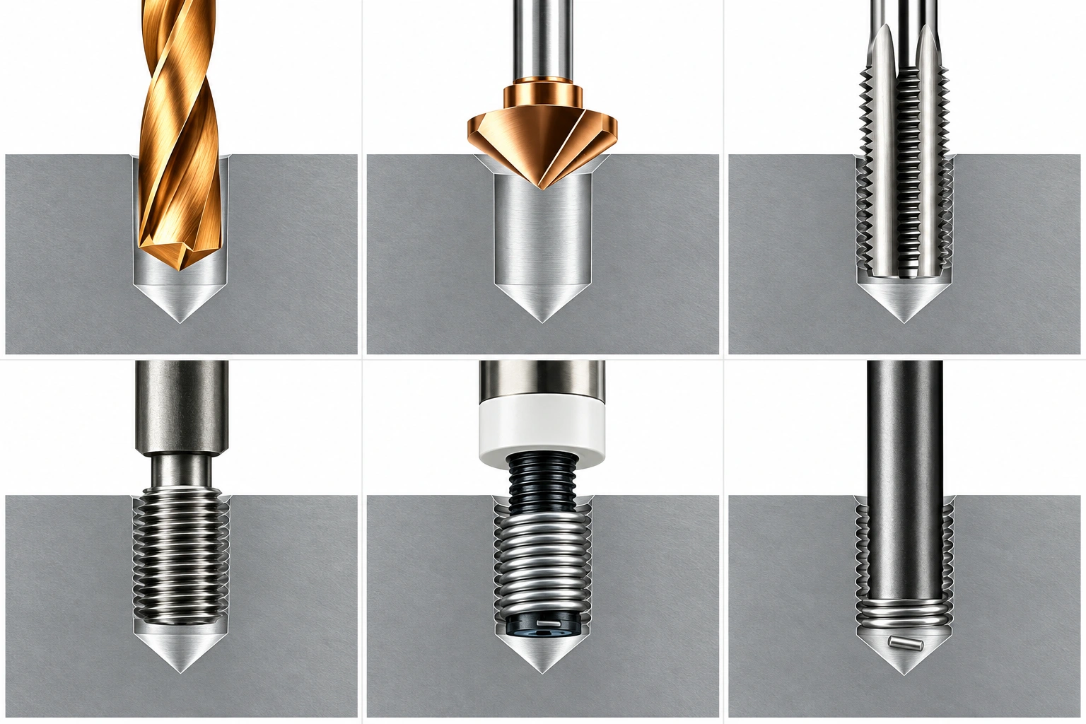
Set drilling diameter and depth for the thread size, parent material and blind-hole allowance. Maintain alignment and remove chips.
Confirm the pilot-hole dimensions before machining.Chamfer or deburr the entry as specified to provide a smooth start for the insert. Do not transfer chamfer angles or diameters between different systems.
Chamfer requirements depend on the selected insert system and drawing.Use a matching STI tap to produce the installation thread. Cutting or forming must be compatible with the parent material and insert system.
A conventional screw tap of the same nominal size is not a substitute.Clean the hole and use a matching STI gauge to check the installation thread. If coating or treatment follows, reassess its dimensional effects.
This checks the installation hole before the insert is fitted.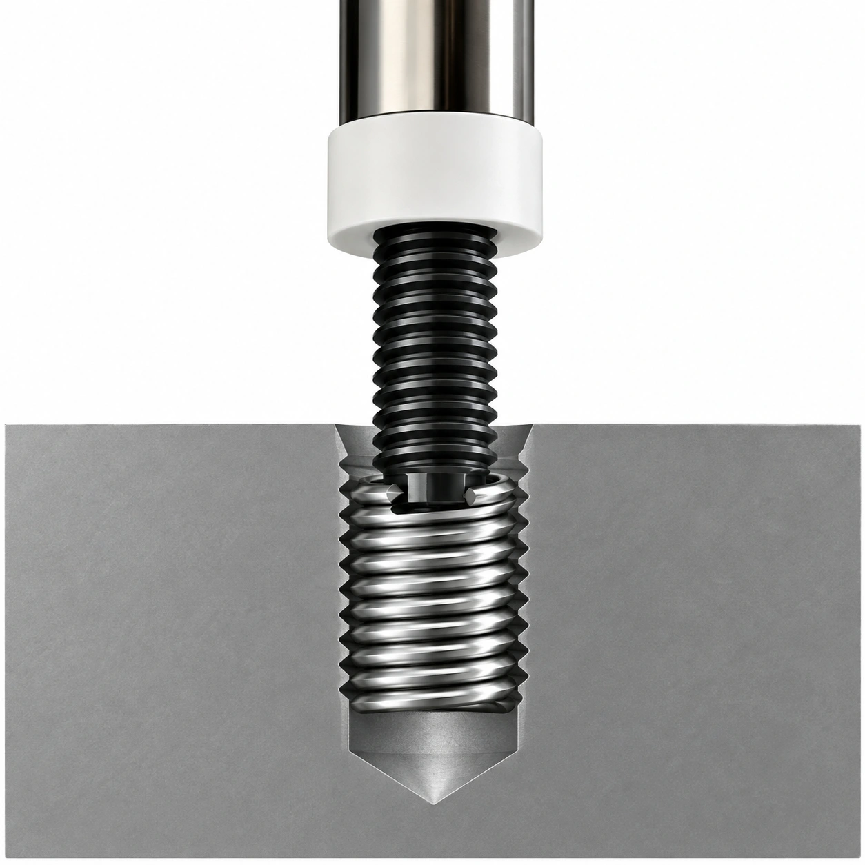
Engage the notch with a matching tangless tool, install smoothly to the specified depth, then withdraw the tool as instructed.
Set the depth according to the drawing, entry geometry and tool depth stop.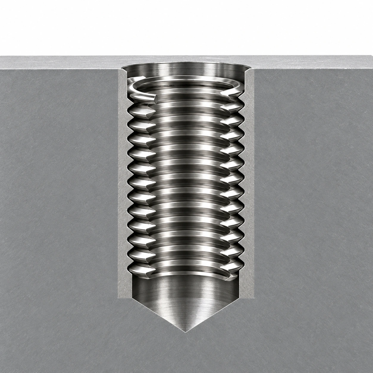
Check position, insert condition and hole cleanliness. Tangless installation has no tang break-off or recovery step, but final inspection is still required.
Follow the locking insert's acceptance procedure; do not force a standard GO gauge through a locking coil.Tool shapes are process illustrations. Images are not to scale and do not replace tool drawings or process documents. Hole preparation, chamfer, installation depth and acceptance requirements must follow approved drawings and tool instructions.
This page explains general tangless wire-insert principles. Specific sizes and processes must follow approved ZCOIL drawings.
CONFIGURATION
Choose a preferred configuration and add thread size and operating conditions. This is an engineering enquiry, not a confirmed supply configuration.
Confirm metric or inch thread, diameter and pitch.
Determine from engagement length and blind-hole clearance.
Discuss media, temperature and mating screw.
Confirm the tool tip matches the tangless drive notch.
KNOWLEDGE & RESOURCES
Not on size alone. The driving mechanisms differ, so the tool's intended application must be checked.
Wire inserts require a matching installation thread. A standard tapped hole for the screw is not an STI insert installation hole.